ch
ch English

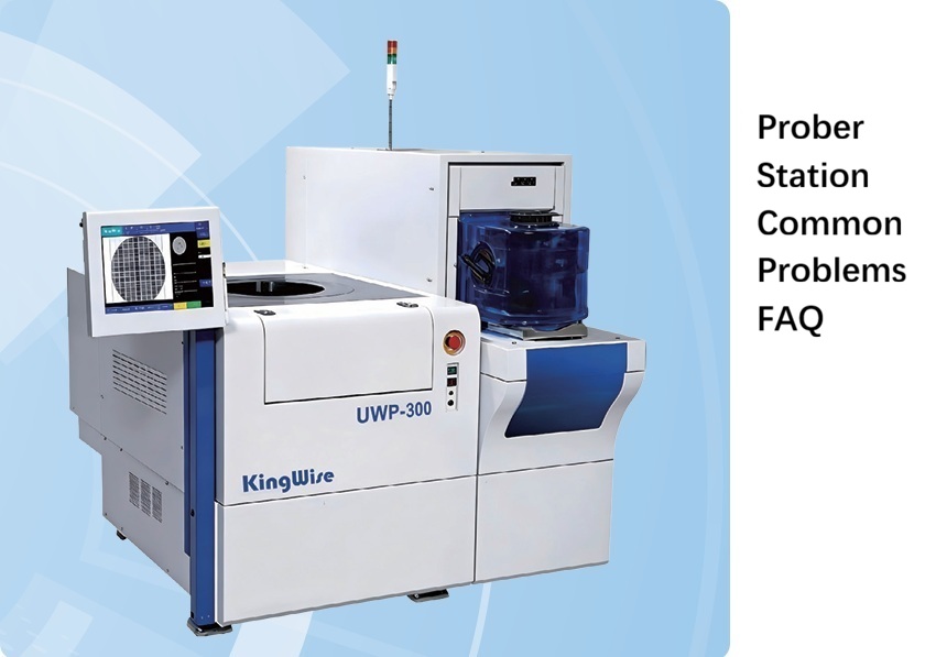
Prober Station Common Problems FAQ
This document focuses on the most frequent critical faults of high-end automatic probe stations in actual production scenarios, excludes basic operation-related content, and directly targets key issue scenarios that impact tool uptime and test yield. All content strictly conforms to the official equipment troubleshooting manual.
1. Core Faults in Software Loading Phase
These problems directly block equipment startup and are the most frequent issues after production line restart:
Error Alarm: System resource loading error, please contact maintenance personnel for processing!
Alarm Cause: Hardware resource loading failure or configuration file reading exception when launching the software
Handling Method: First locate the hardware loading abnormality point according to the log prompt. If the issue cannot be resolved after self-inspection, directly contact the equipment maintenance personnel for processing
Error Alarm: Loader program load failed! Motion controller load failed!
Alarm Cause: The motion control card failed to complete initialization normally
Handling Method: Prioritize checking if the equipment emergency stop button is in the pressed state, release the emergency stop button and retry loading. If the fault still cannot be eliminated, contact maintenance personnel
Error Alarm: IO configuration file does not exist
Alarm Cause: The IO configuration file is lost, or the reading path of the parameter configuration folder is set incorrectly
Handling Method: Verify that the corresponding IO configuration file exists in the software directory, restore the file path or recover the lost file to resolve the issue
2. Core Faults in Equipment Initialization Phase
These problems will prevent the equipment from entering the standby ready state, directly interrupting the production preparation process:
Error Alarm: Loader motion control card initialization failed
Alarm Cause: The emergency stop is not fully released, or there is a hardware abnormality in the motion control card
Handling Method: Perform full-system power-off and re-power-on, then launch the software to proceed with the initialization operation to recover
Error Alarm: Total vacuum / total air pressure does not reach the required value
Alarm Cause: The vacuum/air pressure of the external supply pipeline is insufficient, the corresponding vacuum/pressure gauge has a hardware fault, or the associated IO module is abnormal
Handling Method: Check in sequence whether the vacuum/air pressure of the external supply pipeline meets the standard, confirm the working status of the main gauge, and finally verify whether the corresponding IO point is triggered normally
Error Alarm: X/Y/Z/R axis homing timeout
Alarm Cause: Obstacles are triggered during the homing operation, and the preset waiting time is exceeded
Handling Method: Locate the specific cause that blocks homing according to the operation log and resolve it. If the homing failure still occurs after secondary initialization, contact maintenance personnel
3. Core Faults in New Cassette Wafer Cassette Loading Phase
These problems mostly occur during the loading of the entire batch of wafers, directly causing the batch production to fail to start:
Error Alarm: Wafer scan reading data failed, no wafer is currently detected
Alarm Cause: No valid wafer data is obtained during the wafer scanning process
Handling Method: Verify if wafers are actually placed in the cassette, and confirm that the scanning sensor signal is in a normal working state
Error Alarm: Wafer scan result is abnormal, overlapping wafers/misaligned layers are detected
Alarm Cause: The wafer scanning analysis result determines that the wafers are stacked and misplaced
Handling Method: Open the cassette to confirm the placement status of internal wafers, adjust the wafer thickness identification range in the scanning parameters, and re-execute the scanning process
Error Alarm: Wafer scan result is abnormal, the wafer position difference exceeds the tolerance range
Alarm Cause: The wafer placement position analyzed by the scanning process exceeds the tolerance threshold preset by the system
Handling Method: Check if the wafer placement in the cassette is offset, correct the settings of the starting position, layer spacing and position tolerance in the scanning parameters, and re-scan
4. Core Faults in Fully Automatic Wafer Loading Phase
These problems directly affect the success rate of wafer transfer, and are high-risk scenarios that cause wafer chipping and dropping:
Error Alarm: Failed to find Wafer Notch/Flat, the wafer rotates for more than one cycle without locating the Notch/Flat
Alarm Cause: Abnormal execution of the wafer notch/flat positioning identification process
Handling Method: Adjust the relevant identification parameters for Notch/Flat searching, switch to manual mode to complete the Notch/Flat identification and positioning
Error Alarm: Camera image timeout
Alarm Cause: The visual camera image acquisition is interrupted during the wafer loading process
Handling Method: Use the supporting debugging software of the professional industrial camera to confirm that the camera parameter configuration is compliant, troubleshoot if there are consecutive error frames, and optimize the network configurations such as the giant frame and connection speed of the network port
Error Alarm: Wafer ID recognition failed Vision recognition failed / Verification failed
Alarm Cause: The visual recognition of the wafer serial number is wrong, or the recognition result cannot pass the verification rule
Handling Method: Adjust the Wafer ID recognition parameters to improve recognition accuracy, manually test if the recognized ID can pass system verification, and confirm that the ID characters on the wafer surface are not worn
Error Alarm: After the upper arm places the wafer onto the Prober, there is still a Wafer that has not been separated on the arm
Alarm Cause: The vacuum on the arm side is not released after the wafer placing action is completed, and the wafer is not completely transferred to the Chuck
Handling Method: Verify the signal status of the arm vacuum sensor, and re-calibrate the teaching coordinates of the Prober side wafer receiving position
Error Alarm: Chuck vacuum detection failed
Alarm Cause: No effective vacuum suction is established on the Chuck after wafer placement
Handling Method: Check the on-off status of the Chuck vacuum pipeline, and confirm that the reading of the Chuck vacuum digital display meter meets the process requirements
5. Core Faults in Find Wafer Center Phase
These problems will directly lead to subsequent wafer alignment deviation, affecting the full-wafer test accuracy:
Error Alarm: Failed to find wafer center: No vacuum signal on the Chuck stage!
Alarm Cause: The Chuck did not detect an effective vacuum suction signal before the wafer positioning process started
Handling Method: Immediately confirm the Chuck vacuum establishment status, and verify that the reading of the Chuck vacuum digital display meter meets the standard
Error Alarm: Failed to find wafer center, the edge position exceeds the preset range
Alarm Cause: The calculated wafer edge coordinate by vision exceeds the reasonable threshold set by the system
Handling Method: Visually confirm if the placement position of the current wafer on the Chuck is offset, and retry the positioning process after eliminating the wafer placement abnormality
Error Alarm: Failed to find wafer center
Alarm Cause: Vision cannot identify the boundary contour between the Chuck and the wafer, resulting in complete failure of wafer edge positioning
Handling Method: Re-adjust the relevant parameters for wafer edge identification. If parameter optimization does not work, contact equipment maintenance personnel
6. Core Faults in Wafer Alignment Phase
These problems directly determine the die alignment accuracy, and are the core inducement for unsatisfactory probe test yield:
Error Alarm: Fine alignment cannot be executed before finding the wafer center
Alarm Cause: Wrong sequence of operation procedures, the fine alignment is started before completing the wafer four-side detection and confirming the wafer center
Handling Method: First execute the process to complete the wafer four-side scanning, confirm the wafer center coordinate, then start the Wafer Alignment fine alignment operation
Error Alarm: Fine alignment failed: Auto-focus on alignment pattern failed / Timeout
Alarm Cause: The auto-focus process fails when identifying the pre-registered alignment mark
Handling Method: Re-register the alignment template in an area with clear pattern and no dirt, and synchronously optimize the relevant operation parameters of auto-focus
Error Alarm: Fine alignment failed: The alignment pattern cannot be matched at the registered coordinate position
Alarm Cause: The pattern in the current field of view does not match the pre-registered alignment template
Handling Method: Check if there is dust covering the position where the alignment template is registered, and re-register the alignment template in a clean and clear area
Error Alarm: Fine alignment failed: Horizontal alignment failed / Failed to calculate the die array
Alarm Cause: The wafer horizontal pulling alignment fails, or the system cannot normally calculate the wafer die array coordinates
Handling Method: Re-select a clear area to register the alignment template, reset the Index X/Y step parameters of the wafer and retry the process
7. Core Faults in Needle Alignment Phase
These problems are directly related to the probe contact accuracy, and can avoid batch needle shifting and probe damage issues:
Error Alarm: Needle alignment detection failed: The Prober top cover is not locked
Alarm Cause: The equipment upper cover safety door is not completely closed, triggering the safety interlock to forbid the start of the needle alignment process
Handling Method: Confirm that the Prober top cover is completely closed, and verify that the sensor signal corresponding to the Prober top cover safety door lock is normal
Error Alarm: Needle alignment detection failed: Pad registered data import failed / Selected data is empty
Alarm Cause: The system cannot read the pre-registered test Pad point information before the needle alignment process starts
Handling Method: Confirm that the Pad point registration operation has been completed, and re-execute the complete Pad registration process when data is abnormal
Error Alarm: Needle alignment detection failed: Needle manual alignment teaching is not completed
Alarm Cause: The pre-position manual needle alignment teaching step is not completed before the fully automatic needle alignment process starts
Handling Method: Confirm that the manual needle alignment teaching has been fully executed, and re-go through the manual needle alignment process when the teaching data is missing
Error Alarm: Needle alignment warning: Failed to match the first pattern, Rotation compensation failed
Alarm Cause: The vision cannot match the preset template during the probe card angle compensation alignment process
Handling Method: Confirm that the pattern in the alignment template area is clear and not worn, replace the area to re-register the template and retry
8. Core Faults in Probing Phase
These problems will directly interrupt the mass production test process, causing batch production delay:
Error Alarm: Probing failed: The Prober top cover is not locked
Alarm Cause: The safety door protection is not released before the test process starts
Handling Method: Check the closing status of the Prober top cover, and confirm that the safety door lock signal is triggered normally
Error Alarm: Failed to move to the first Die / XYZR axis motion timeout
Alarm Cause: The wafer Map data parsing is abnormal, or hardware obstacles are triggered during the axis group operation, resulting in motion interruption
Handling Method: Directly contact equipment maintenance personnel to troubleshoot the root cause of motion abnormality, avoiding hard movement that causes the probe card to scratch the wafer
9. Core Faults in Unload / Wafer Unloading Phase
These problems mostly occur during the unloading process after the full wafer batch test is completed, preventing wafer dropping after failed wafer picking:
Error Alarm: There is no Wafer on the current Chuck, the instruction is abnormal
Alarm Cause: Before the wafer unloading process starts, the system detects that the Chuck has no vacuum signal for wafer suction
Handling Method: Confirm the vacuum status of the Prober Chuck, and check if there is an abnormality that the wafer falls off in advance
Error Alarm: After the lower arm takes the Wafer from the Prober, no vacuum signal is detected on the arm
Alarm Cause: The arm fails to establish effective vacuum after the wafer picking action is completed, there is a wafer dropping risk
Handling Method: Verify the working status of the lower arm vacuum sensor, and re-calibrate the teaching coordinates of the Prober side wafer picking position
Error Alarm: A Wafer already exists on the specified cassette layer
Alarm Cause: During wafer loading into the cassette, the system determines that there is already a wafer placed on the target cassette layer
Handling Method: Troubleshoot whether there is a logic error in the cassette storage data, contact the program developer to confirm the cause of the data abnormality
10. Equipment Safety Red Line Notes
High-end probe stations belong to high-precision semiconductor test equipment. The following rules must be followed during operation to avoid tool damage and personal injury:
Only certified personnel who pass the training assessment can operate the tool; during the operation process, it is strictly forbidden to extend any part of the body into the equipment motion stroke, press the emergency stop button immediately once abnormality is found
Non-professional maintenance personnel are forbidden to open the equipment shell and modify hardware configurations without permission, all maintenance operations must be executed by certified engineers
The power supply and air pressure supply must be kept stable during equipment operation, and sudden interruption of external energy supply is strictly prohibited
After equipment handling, core parameters such as flatness and axis positioning accuracy must be re-calibrated, and the equipment can be put back into production only after confirming that the accuracy meets the requirements
 Prober Station Common Problems FAQ-OSI.pdf